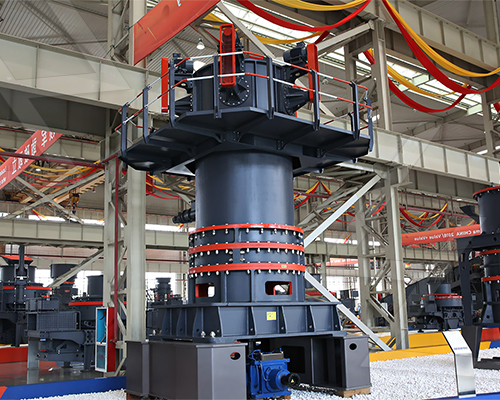
A hydraulic circuit diagram for a vertical roller mill (VRM) typically includes components that control grinding pressure, mill vibration, and hydraulic positioning of the grinding rollers. Below is a simplified breakdown of key elements:
—.jpg)
Key Components in a VRM Hydraulic Circuit
1. Hydraulic Power Unit (HPU)
– Pump (gear/piston pump)
– Pressure relief valve
– Accumulator (for pressure stabilization)
– Filters & coolers
2. Hydraulic Cylinders
– Actuate grinding rollers against the mill table.
– Equipped with position sensors for feedback control.
3. Pressure Control Valves
– Proportional or servo valves regulate grinding force.
– Pressure sensors ensure optimal load distribution.
4. Damping System
– Hydraulic accumulators/shock absorbers reduce vibrations.
5. Directional Control Valves
– For lifting/lowering rollers during maintenance or startup.
6. Safety Components
– Check valves (prevent backflow).
– Pressure switches (overload protection).
—
Simplified Hydraulic Circuit Diagram
“`
┌───────────────────────────────────────┐
│ HYDRAULIC POWER UNIT │
│ ┌─────────┐ ┌─────────┐ │
│ │ PUMP ├───►│FILTER/COOLER │
│ └─────────┘ └─────────┘ │
│ ▲ ▼ │
└──────┬────┴───────────────┬──────┬─────┘
│ │ │
▼ ▼ ▼
┌─────────────────┐ ┌───────────────┐ ┌───────────────┐
│ PRESSURE CONTROL│ │ ACCUMULATOR │ │ DIRECTIONAL │
│ VALVE ◄──┤ (Stabilizes) ◄──┤ CONTROL VALVE ├──►CYLINDERS
│ (Adjusts force) ├──► ├──►(Lift/Lower) ▲
└─────────────────┘ └───────────────┘ └───────────────┘ │
▼
┌───────────────┐
│ GRINDING │
│ ROLLERS │
└───────────────┘
“`
—
Functionality
– Grinding Pressure Control: Hydraulic pressure adjusts roller force based on material hardness and feed rate.
– Vibration Damping: Accumulators absorb shocks from uneven grinding.
– Roller Positioning: Cylinders retract rollers during idle or maintenance.
—
Additional Notes
– Modern VRMs use electro-hydraulic systems with PLCs/PID controllers for precise pressure regulation.
– Redundant safety valves prevent excessive loading.
For detailed schematics, refer to OEM manuals (FLSmidth, Loesche, Pfeiffer) as designs vary by manufacturer. Would you like specifics on any component?


Leave a Reply