Momentum transfer gyrostats (or gyroscopic momentum transfer devices) are systems that use the principles of gyroscopic motion to exchange angular momentum between rotating bodies, often for attitude control or stabilization in spacecraft, satellites, and other aerospace applications. Here’s a breakdown of the key concepts:
 1. Basic Principle
– A gyrostat consists of a rotor (flywheel) spinning at high angular velocity inside a rigid or flexible structure.
– When torque is applied to the rotor’s axis (e.g., by gimbal motors or reaction wheels), it generates a gyroscopic reaction torque perpendicular to the applied force (due to Euler’s equations for rigid body rotation).
– This allows controlled momentum exchange between the rotor and the spacecraft, enabling precise attitude adjustments without expending propellant.
 2. Applications
– Spacecraft Attitude Control: Gyrostats (or control moment gyros, CMGs) are used to reorient satellites and space stations (e.g., ISS uses CMGs for stabilization).
– Inertial Guidance Systems: Used in missiles and drones for stability.
– Energy Storage: Some systems store kinetic energy in spinning rotors for later momentum transfer.
3. Types of Gyroscopic Momentum Transfer Devices
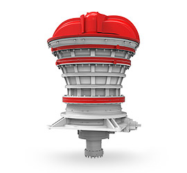
– Control Moment Gyros (CMGs): Use a gimbaled flywheel to produce large torques by tilting the spin axis.
– Reaction Wheels: Simpler than CMGs; change spacecraft orientation by varying rotor speed (no gimbal).
– Momentum Wheels: A single spinning wheel used primarily for stabilization rather than large maneuvers.
4. Key Equations
The torque produced by a gyrostat follows:
\[
\tau = \mathbf{\dot{H}} = I \cdot \mathbf{\alpha} + \mathbf{\omega} \times (I \cdot \mathbf{\omega})
\]
where:
– \(\tau\) = Torque
– \(H\) = Angular momentum (\(H = I\omega\))
– \(I\) = Moment of inertia
– \(\omega\) = Angular velocity
– \(\alpha\) = Angular acceleration
For CMGs, the output torque is:
\[
\tau_{CMG} = \dot{\gamma} \times H_{wheel}
\]
where \(\dot{\gamma}\) is the gimbal rate and \(H_{wheel}\) is the rotor’s angular momentum.
5. Challenges
– Gim


Leave a Reply