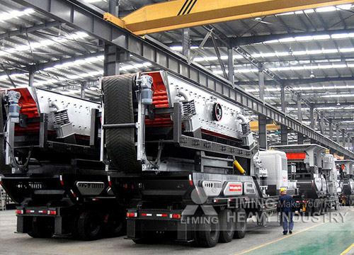
A grinding unit flowsheet outlines the process flow of a grinding circuit, typically used in mineral processing, cement production, or other industries where size reduction is critical. Below is a generalized flowsheet for a grinding unit, along with key components and explanations.
—
.jpg) Typical Grinding Unit Flowsheet
Typical Grinding Unit Flowsheet
1. Feed Material
– Crushed ore/raw material (e.g., limestone, clinker, or ore) is fed into the grinding circuit.
– Particle size: Typically <25 mm (varies based on mill type).
2. Grinding Mill
– Primary equipment:
– Ball Mill (for fine grinding, closed-circuit).
– Vertical Roller Mill (VRM) (common in cement/powder grinding).
– Rod Mill (coarse grinding).
– May operate in open or closed circuit with classifiers.
3. Classification System
– Dynamic Separator (for VRM) or Air Separator.
– Hydrocyclones/Screens (for wet/dry classification).
– Oversize material is returned to the mill (recirculation load), while fine product proceeds.
4. Product Collection
– Ground material is collected via:
– Bag filters/ESP (for dry processes).
– Thickeners (for wet processes).
5. Auxiliary Systems
– Dust collection, cooling (if needed), and material transport (conveyors/buckets).
—
Example Flowsheet Diagrams
# (1) Closed-Circuit Ball Mill Grinding
“`
[Feed Hopper] → [Conveyor] → [Ball Mill] → [Hydrocyclone] →
↑(Underflow) ↓(Overflow)
└───────────────┘ [Product Storage]
“`
 # (2) Vertical Roller Mill (VRM) Circuit
“`
[Feed Bin] → [VRM] → [Dynamic Separator] →
↑(Coarse Reject) ↓(Fine Product)
└─────────────────┘ [Bag Filter] → [Storage]
“`
—
Key Parameters to Monitor
– Circulating Load: % of material returned to the mill.
– Particle Size Distribution: Target fineness (e.g., 80% passing 45 µm for cement).


