

A mineral processing diagram (or flowsheet) outlines the steps involved in extracting valuable minerals from ore. Below is a simplified overview of a typical mineral processing flow diagram, covering key stages from raw ore to final concentrate.
—
General Mineral Processing Flow Diagram
1. Ore Extraction (Mining)
– Open-pit or underground mining delivers raw ore to the processing plant.
2. Crushing & Screening
– Primary Crushing: Jaw or gyratory crushers reduce large ore chunks.
– Secondary/Tertiary Crushing: Cone crushers or impact mills further break down material.
– Screening: Vibrating screens classify particles by size (oversize is recirculated).
3. Grinding (Comminution)
– Ball mills or rod mills grind crushed ore into fine particles (<100–300 µm) to liberate minerals.
4. Classification
– Hydrocyclones or spiral classifiers separate particles by size/density; coarse material is returned for regrinding.
5. Separation (Beneficiation)
– Gravity Separation: For dense minerals (e.g., gold, tungsten) using jigs, shaking tables, or spirals.
– Magnetic Separation: For iron ore or magnetite using drum magnets.
– Froth Flotation: For sulfides (e.g., copper, lead) using chemicals and air bubbles to float target minerals.
– Leaching: For gold/uranium (e.g., cyanide/acid dissolves metals for later recovery).
6. Dewatering
– Thickeners, filters (e.g., vacuum belt filters), or centrifuges remove water from concentrates/tailings.
7. Tailings Management
– Waste slurry is stored in engineered ponds; water may be recycled.
8. Final Product
– Dried concentrates are shipped to smelters/refineries for metal extraction.
—
 Example: Simplified Copper Ore Processing
1. Mining → 2. Crushing → 3. Grinding → 4. Froth Flotation → 5. Concentrate Thickening → 6. Smelting → 7. Electrorefining (for pure copper).
—
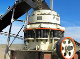 Diagram Tools
– Use software like *Metso Outotec’s HSC Sim*, *CAD*, or *Visio* to design detailed flowsheets