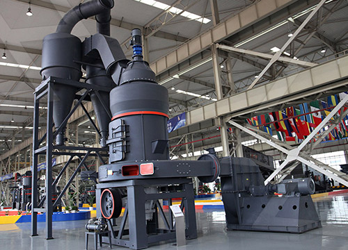
Here’s a simplified diagram and explanation of a hammer mill crusher:
—
 Hammer Mill Crusher Diagram & Key Components
1. Feed Hopper
– Where raw material enters the mill.
– May include a feeder (screw or vibratory) to control input rate.
2. Rotor Assembly
– Central rotating shaft with hammers (swinging or fixed).
– Spins at high speed (typically 1,000–3,000 RPM).
3. Hammers
– Blunt or sharp metal pieces attached to the rotor.
– Strikes and shatters material upon impact.
4. Crushing Chamber
– Enclosed space where hammers crush material against:
– Screen/Grid Bars: Perforated metal screen sizing the output.
– Breaker Plates: Optional wear-resistant liners to enhance crushing.
5. Discharge Chute
– Crushed material exits through the screen openings.
6. Drive Motor & Pulley System
– Powers the rotor via belts or direct drive.
7. Dust Collection Port (Optional)
– Connects to a baghouse/cyclone to control dust.
—
Simplified Diagram (Text-Based):
“`
_________________________
| FEED HOPPER |
|_________________________|
|
V
_________________________
| |
| ROTOR + HAMMERS (→) | <– Spinning Direction
| |
| [==== SCREEN ====] | <– Perforated Sieve
|_________________________|
|
V
_________________________
|  DISCHARGE CHUTE |
|_________________________|
“`
—
How It Works:
1. Material enters via the hopper.
2. Rotating hammers strike and throw particles against the screen/liners.
3. Particles are crushed until small enough to pass through the screen holes.
4. Output size depends on screen aperture and hammer speed.
—
Applications:
– Grain processing, biomass shredding, mineral crushing, recycling (e.g., electronics, metals).
Let me know if you need a more detailed schematic or CAD-style illustration!


