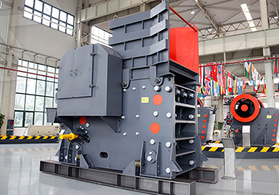
Here’s a simplified diagram of a typical hammer mill machine with labeled components:
—
.jpg) Hammer Mill Diagram
Hammer Mill Diagram
*(Top View / Cross-Sectional View)*
1. Hopper (Feed Inlet)
– Where raw material enters the mill.
2. Rotor Assembly
– Central rotating shaft with hammers attached.
3. Hammers (Swinging or Fixed)
– Blades that strike and shred the material.
4. Screen (Perforated Sieve)
– Determines final particle size; material exits once small enough.
5. Grinding Chamber
– Enclosed space where hammering occurs.
6. Discharge Outlet
– Processed material exits here (e.g., to a cyclone or bag).
7. Drive Motor & Pulley System
 Powers the rotor at high speed (typically 1,500–3,000 RPM).
—
Key Features:
– Material Flow: Feed → Hammer impact → Screen filtration → Discharge.
– Particle Control: Screen hole size adjusts fineness.
Simplified Sketch:
“`
___________________________
/ \
| [Hopper] |
\_________▲_________________/
| Feed Material
_________▼_________
| Rotor & Hammers |←───[Motor]
|◄┼─────┬─────┼► | (Driveshaft)
| │ │ │ |
| ▼ ▼ ▼ |
|[Screen Grid] |───▶ [Discharge]
└───────────────────┘
“`
—
Notes:
– Hammers pivot or are fixed to the rotor for impact grinding.
– Air assist may be used for material evacuation in some models.
Let me know if you’d like a more detailed schematic or specific part explanations!


Leave a Reply