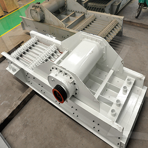
Here’s a simple principle sketch and explanation of a fluidized bed dryer:
 Fluidized Bed Dryer – Principle Sketch
“`
_________________________
| |
| Exhaust Gas |
| ↑ |
|_________________________|
||
+———————–+
| Filter / Cyclone |
+———————–+
↑
Hot Air → || (Fluidizing Air)
+———————–+
| Perforated Plate | ← Bed Material (Wet Particles)
+———————–+
↑
+———————–+
| Air Heater / Blower |
+———————–+
“`
 Key Components & Working Principle:
1. Perforated Plate (Distribution Plate):
– Supports the wet solid particles while allowing hot air to pass through.
2. Fluidizing Air (Hot Air):
– Forced upward through the plate at a velocity sufficient to suspend particles (fluidization).
3. Bed of Wet Particles:
– The material behaves like a boiling liquid due to fluidization, ensuring uniform drying.
4. Exhaust System (Filter/Cyclone):
– Removes fine particles from the exhaust gas.
5. Air Heater & Blower:
– Supplies controlled-temperature air for drying.
Fluidization Principle:
– When air velocity exceeds the minimum fluidization velocity, solid particles become suspended, increasing heat and mass transfer efficiency.
– Ensures rapid, uniform drying due to intense mixing.
Would you like a more detailed diagram or an explanation of any specific part?


